Table of contents

1. Introduction
2. Overview Technical Details
3. Components
4. Calculated technical values
5. Sources
Introduction

The F-1 rocket engine was developed by Rocketdyne specifically for the Apollo program. Five F-1 engines propelled the Saturn-V launch vehicle, using RP-1 and Liquid Oxygen (LOX) as propellants. In January 1957, NASA contacted Rocketdyne to develop a combustion chamber experiment to break the 1000000 pounds of thrust barrier [1].

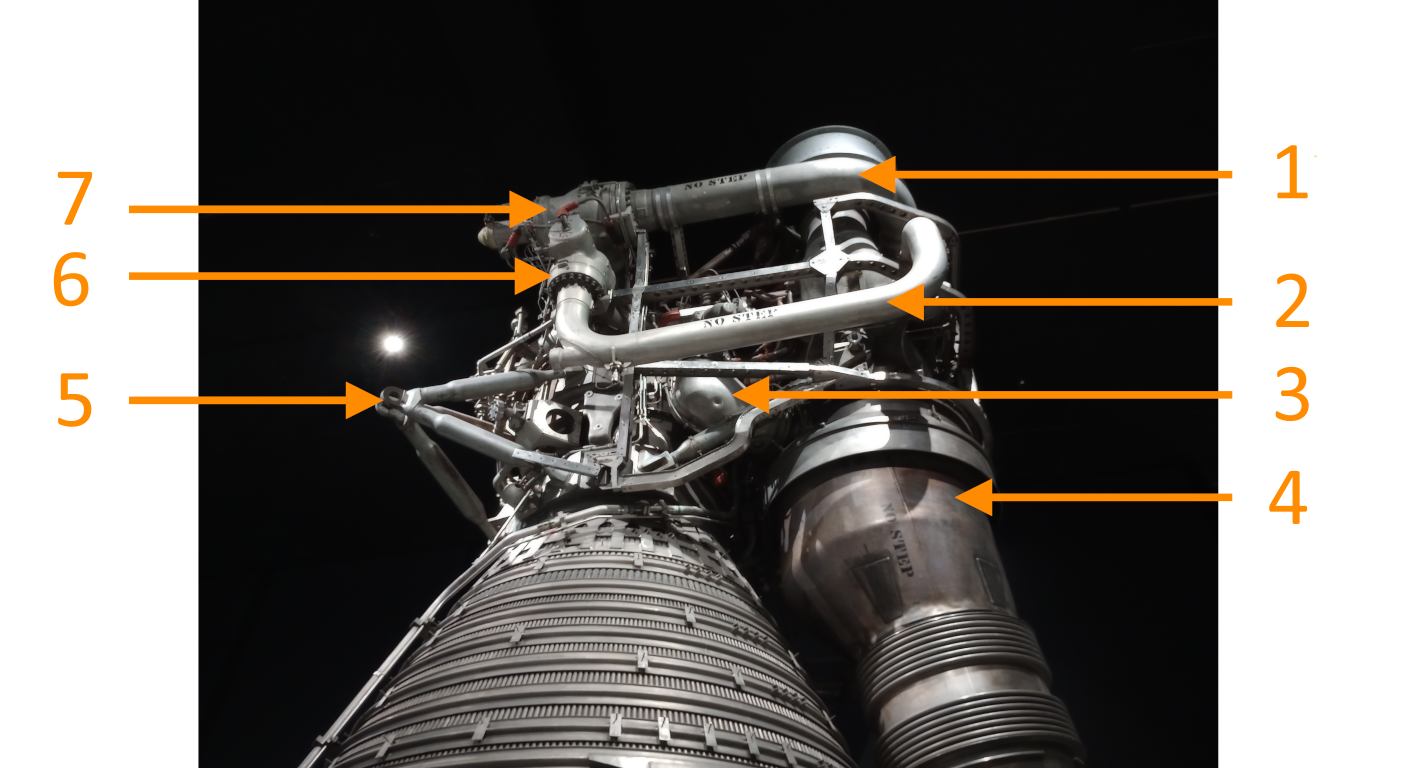
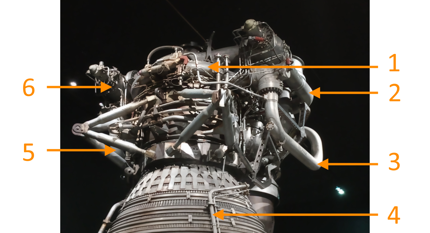
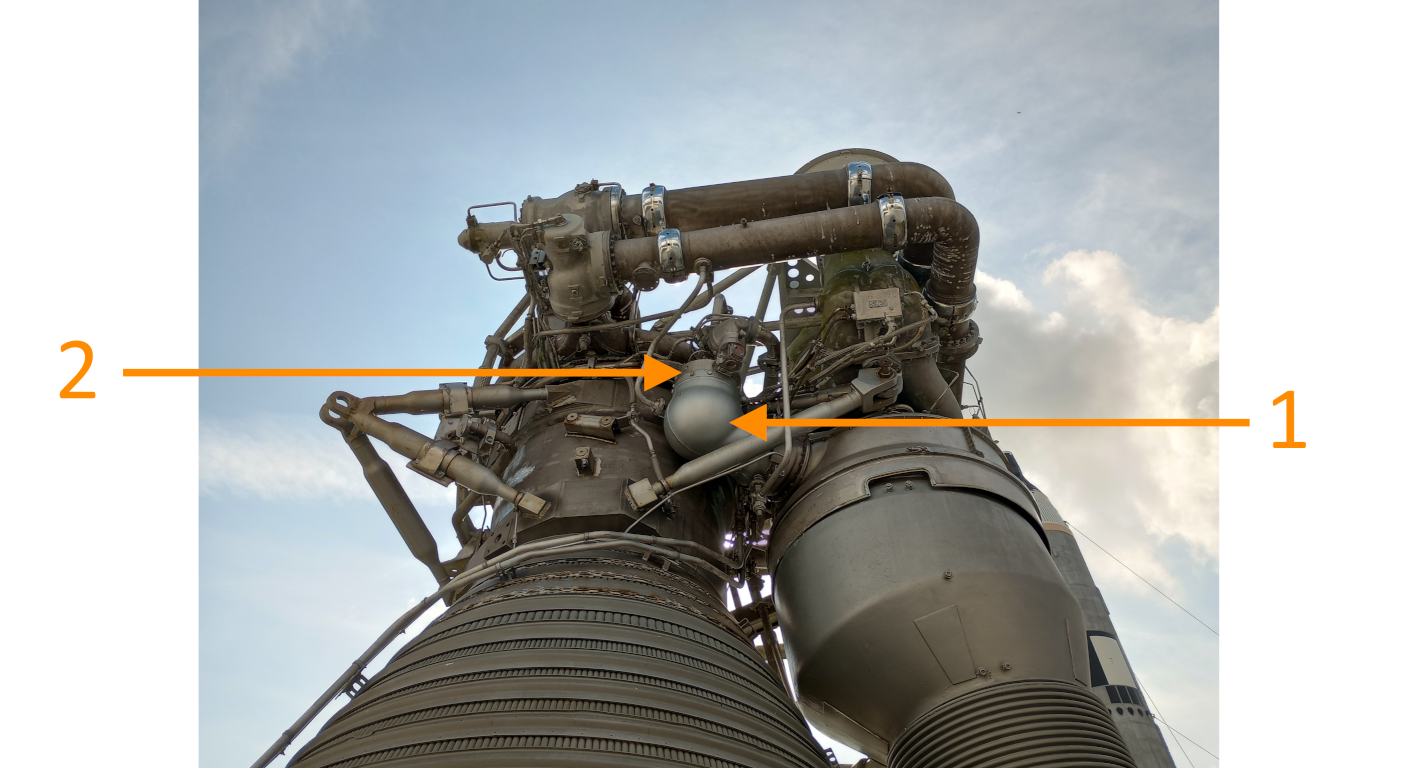
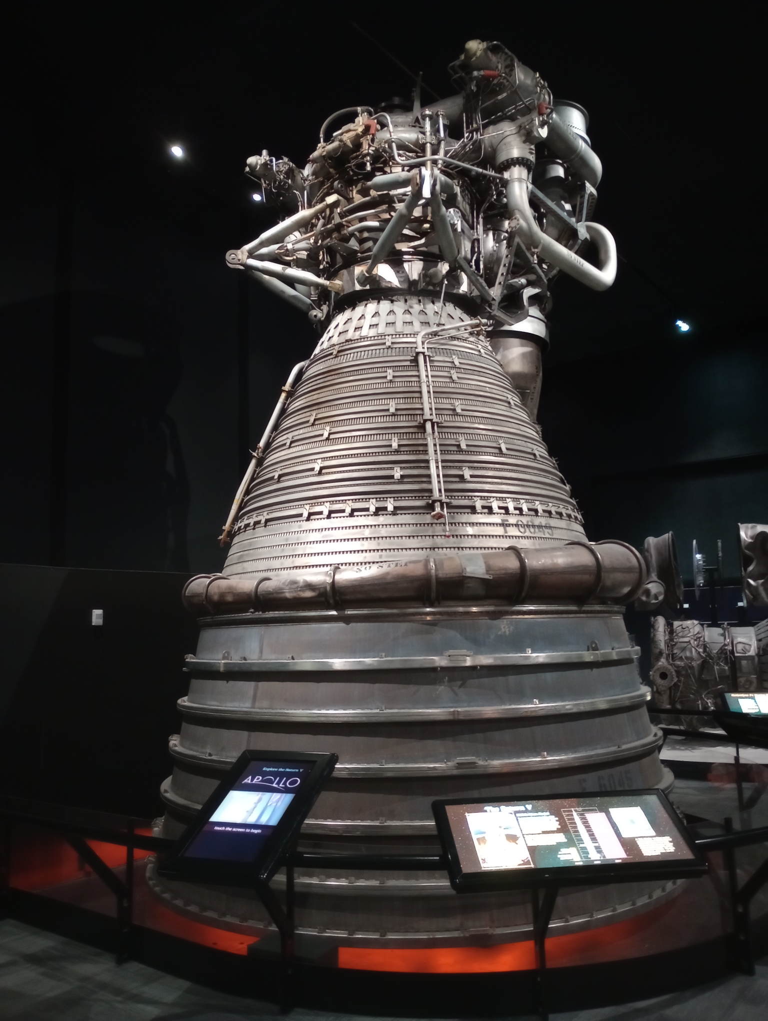
Before this date, Rocketdyne conducted studies of such a rocket engine in anticipation of a launch vehicle requiring such thrust levels. In April 1965, five F-1 engines were assembled on the first stage of the Saturn-V for testing purposes. On 6 September 1966, the F-1 rocket engine passed the qualification testing for manned use. See Figure 1 of an image of the F1 engine [1].


Figure 1: The F-1 rocket engine [2]


Overview technical details
Different sources are used to gather information about the technical details of an H-1 rocket engine. The found details are summarized in the table below:

Parameter Value Unit Source
Chamber pressure 1125 / 77.6 psi / bar [3]
Propellant RP-1 (fuel) and LOX (oxidzer) [-] [3]
Oxidizer to fuel ratio 2.27 : 1 [-] [3]
Thrust 1522000 / 6773 lb / kN [3]
Isp 263.5 sec [3]
Expansion ratio 16 [-] [3]
Mass flow 5737 / 2602.3 [lb/s / kg/s] [3]
Rotational speed LOX and RP-1 pumps 5492 rpm [3]
Rotational speed turbine 5492 rpm [3]
Turbine power 53146 hp [3]

Components

The author had the opportunity to go to the Museum of Flight and Kennedy Space Center, to visit the displayed F-1 engines. During these visits, a number of detailed photos were taken of this engine.

In Figure 2, the top section of the F-1 engine is shown. This figure shows that this engine is equipped with a gas generator to power the turbopump assembly (also known as a gas generator cycle). The turbopump assembly has on top the LOX pump, in the middle the RP-1 pump and at the bottom the turbine. The hot gases from the gas generator that powers the turbine are collected in the turbine exhaust duct. [3]


Figure 2: Overview of the top section of the F-1 engine [2]
1: High-pressure LOX duct
2: High-pressure RP-1 duct
3: Gas generator
4: Turbine exhaust duct
5: Gimbal outrigger
6: RP-1 valve
7: LOX valve

It can be seen from Figure 3 that each propellant has 2 supply ducts to the injector. Also, the overboard drain lines are shown in this figure. The overboard drain lines are used to dispose of propellant that has leaked past the seals of some components (such as valves) and to cool the bearings of the turbopump [3].


Figure 3: Overview of the top section of the F-1 engine from a different point of view [2]
1: Fuel inlet manifold
2: No 1. high-pressure LOX duct
3: No 1. high-pressure RP-1 duct
4: Overboard drain line
5: No 2. high-pressure RP-1 duct
6: No 2. LOX valve

The turbine of the F-1 rocket engine consists of 2 turbine wheels. A part of such a turbine wheel can be seen in Figure 4. The type of this turbine is a 2-stage, velocity-compounded, impulse gas turbine.


Figure 4: Part of the turbine wheel [2]

A special item that is on display in the Museum of Flight is the recovered components of a flown F-1 rocket engine. For example, the injector is recovered. The recovered injector can be seen in Figure 5. The injector is divided into 13 compartments to improve combustion stability. It is constructed of different rings, where the LOX (oxygen) and the RP-1 (fuel) are injected in alternating rings. The fuel is injected using a double-fuel on-fuel impingement method. The oxygen is also injected using a double-oxidizer-on- oxidizer impingement method.[3]


Figure 5: Close up of the injector [2]
1: 1 of the 13 compartments
2: Fuel ring
3: Oxidizer ring
4: Fuel ring
5: Oxidizer ring

The gas generator can be better seen at the F-1 engine displayed at Kennedy Space Center. The gas generator consists of a combustion chamber, an injector, and a dual ball valve. It weighs 220 pounds (100 kg) and has a chamber pressure of 980 psi (67.5 bar). It has a mixture ratio of 0.416:1 and a mass flow of 167 lb/s (75.7 kg/s). The combustion temperature is 1453 Fahrenheit (1062 K). [3]


Figure 6: Better view on the gas generator [4]
1: Injector of gas generator
2: Combustion chamber gas generator

Another special item that is on display at the Museum of Flight is the (partly) damaged heat exchanger and nozzle section, as seen in Figure 7. The heat exchanger is responsible for converting liquid oxygen to gaseous oxygen using the warm exhaust gas of the turbine. This gaseous oxygen is used to pressurize the oxygen tank. Additionally, the chilled helium is expanded using the hot exhaust gases of the turbine to pressurize the fuel tank. [3]

In Figure 7, it can also be seen that the nozzle consists of tubular tubes for regenerative cooling. A total of 178 primary cooling tubes are used for an expansion ratio of 3 or smaller. The material Inconel-X was used for the tubing, which had an outer diameter of 28.7 mm. The nozzle with an expansion ratio of 3 and smaller than 10 uses 356 tubes with an outer diameter of 25.4 mm [3].


Figure 7: An unique cross-sectional view of the F1 engine [2]
1: Coils that carry helium or LOX
2: Heat exchanger assembly
3: One of the tubes used for regenerative cooling

The F-1 engine displayed at Kennedy Space Center shows a better view of the turbo pumps. It can be seen in Figure 8 that the oxygen pump and fuel pump are placed in a back-to-back configuration. Both pumps have two outlets. The fuel pump has two inlet ducts, while the oxygen pump has one inlet. [3]


Figure 8: Detailed view of the turbopump assembly [4]
1: One of the inlets for the fuel pumps
2: No 2 fuel high-pressure ducts
3: No 1 fuel high-pressure ducts
4: Fuel pump
5: Oxygen pump

The nozzle is not only cooled by regenerative cooling, but also by film cooling. This can be seen in Figure 9. The section of the nozzle that has an expansion ratio of 10 or smaller is regeneratively cooled. The section of the nozzle that has an expansion ratio between 10 and 16 is film-cooled with a double wand. [3]


Figure 9: Overview for film cooling method [2]
1: Exhaust turbine duct
2: Section cooled by film cooling
3: Duct to supply the hot gas for film cooling
4: Section cooled by regenerative cooling

Calculated technical values

The following technical details are calculated based on the photos and the found technical details (as discussed in section 2).

Propellant details:
Parameter Value Unit
Combustion temperature 3570 K
Exhaust molar mass 22.210 g/mol
γ 1.178 [-]

Performance details:
Parameter Value Unit
C* 1731 m/s
Cf 1.492 [-]
Mass flow 2602 kg/s
Exit pressure 0.565 bar
Mach flow inlet XXX [-]
Correction c* 0.965 [-]
Correction cf 0.965 [-]
Calculated thrust at sea level 6725 kN
Calculated isp at sea level 263.5 sec

Dimensions details:
Parameter Value Unit
Combustion diameter XXX m
Throat diameter 0.859 m
Exit diameter 3.435 m
Contraction ratio XXX [-]
Expansion ratio 16.0 [-]
Inlet angle XXX degrees
Bell angle at throat XXX degrees
Bell angle at exit XXX degrees
Bell angle percentage length XXX %
L* XXX m
Divergent section length nozzle XXX m
Convergent section length nozzle XXX m
Combustion chamber length XXX m
Lenght engine XXX m


Sources

[1]: Saturn V America's rocket to the moon - Eugen Reichl
[2]: Photo's taken at Museum of Flight
[3]: Technical Manual Engine Data F-1 Rocket Engine (Rocketdyne) (From heroicrelics.org )
[4]: Photo's taken at Kennedy Space Center