Table of contents

1. Introduction
2. Overview Technical Details
3. Components
4. Calculated technical values
5. Sources
Introduction

The H-1 engine was developed to propel the first stage of the Saturn 1 and Saturn 1B launch vehicles. This engine used RP-1 as the fuel and liquid oxygen (LOX) as the oxidizer. The development of this engine started in 1957, and the first prototype was tested in 1959. The qualification was completed in 1965, and NASA received the first engine in 1965. [1]

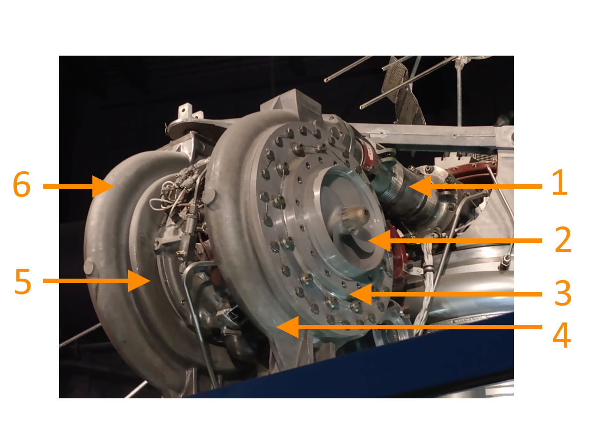
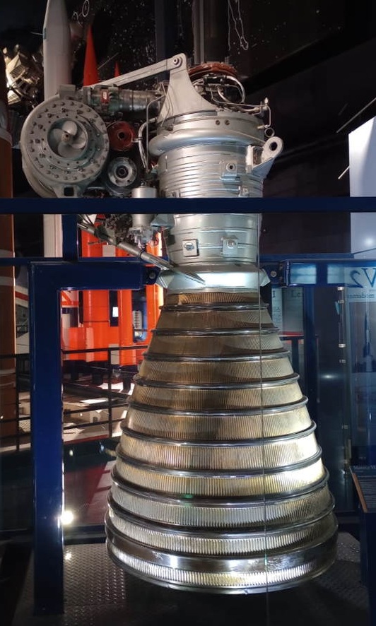
Two variants of the H-1 engine were developed. The variant H-1D had gimbal capabilities, while the variant H-1C had no gimbal capabilities. In total, eight H-1 rocket engines were installed at the first stage. Four inboard engines were the H-1C variant, and the four outboard engines were the H-1D variant. See Figure 1 for an image of the H-1 rocket engine. [1]


Figure 1: The H-1D rocket engine [4]


Overview technical details
Different sources are used to gather information about the technical details of an H-1 rocket engine. The found details are summarized in the table below:

Parameter Value Unit Source
Chamber pressure 700 / 48.2 psi / bar [2]
Propellant RP-1 (fuel) and LOX (oxidzer) [-] [2]
Oxidizer to fuel ratio 2.23 : 1 [-] [2]
Thrust 205000 / 911.8 lb / kN [2]
Isp 263 sec [2]
Expansion ratio 8 [-] [2]
Rotational speed LOX and RP-1 pumps 6537 rpm [3]
Rotational speed turbine 32000 rpm [3]
Turbine power 3739 hp [3]

Components

The autor visisited the Musée de l'Air et de l'Espace. As part of the collection, an H-1D rocket engine is displayed. This provided the opportunity to make detailed photos of the different components of this engine.

As can be seen in Figure 2, the fuel and oxidizer pumps are connected by the same drive shaft. It is also observed that both pumps have a single volute outlet. In Figure 3, it can be seen that the turbine has an offset to both pumps. This is also named an offset turbine configuration. The turbine drives the two pumps through a gearbox.

The turbine is a two stage, pressure compounded type [3].

Figure 2: Overview of the turbopumps for the H-1 engine [4]
1: Outlet pump - high pressure LOX duct
2: LOX impeller - inlet LOX pump
3: LOX pump
4: LOX volute
5: RP-1 pump
6: RP-1 volute


Figure 3: Overview of the turbine side of the rocket enigne [4]
1: Outlet pump - high pressure RP-1 duct
2: Fuel pump
3: Duct that supplies gas for the turbine
4: Gas generator (partly visible)
5: Turbine

In Figure 4, it can be seen that the H-1 rocket engine is equipped with a Fuel Additive Blender Unit. The Fuel Additive Blender Unit is responsible for adding an oxidizing and corrosive inhibitor additive (Oronite 262) to the mixture of RP-1 and LOX. This is then injected into the gearbox assembly for lubrication and cooling purposes. [3]

Two auxiliary drive pads are connected to the turbopump assembly. These drive pads rotate at 4000 rpm. The outboard engines use one of these drive pads to power the main pump. The main pump provides hydraulic pressure. [3]

The thrust chamber consists of 292 longitudinal tubes that carry the RP-1 fuel. The fuel manifold supplies the RP-1 in alternate tubes to the return manifold, followed by the alternate tubes towards the injector. Thus, the thrust chamber consists of 146 pairs of tubes that are used for cooling purposes. Each pair of tubes has 1 tube downwards to the return manifold, followed by 1 tube upwards to the injector. [3]


Figure 4: General overview of the H1 engine [4]
1: Gimbel joint (covered in a dustcap)
2: RP-1 manifold
3: Combustion chamber
4: Nozzle - regenerative cooled
5: Stiffner
6: Fuel Additive Blender Unit
7: Auxurily drive pad
8: LOX pump
9: Auxurily drive pad

The different components must be mounted to the rocket engine, using brackets. These brackets have to withstand the launch environment, which consists of vibration and acceleration. One of these brackets can be seen in Figure 5.


Figure 5: Details of a beautifull designed and casted bracket of the H-1 rocket engine [4]


Calculated technical values

The following technical details are calculated based on the photos and the found technical details (as discussed in section 2).

Propellant details:
Parameter Value Unit
Combustion temperature 3495 K
Exhaust molar mass 21.925 g/mol
γ 1.1768 [-]

Performance details:
Parameter Value Unit
C* 1725 m/s
Cf 1.46 [-]
Mass flow 360 kg/s
Exit pressure 0.87 bar
Mach flow inlet 0.43 [-]
Correction c* 0.967 [-]
Correction cf 0.95 [-]
Calculated thrust at sea level 910.5 kN
Calculated isp at sea level 257 sec

Dimensions details:
Parameter Value Unit
Combustion diameter 0.509 m
Throat diameter 0.405 m
Exit diameter 1.142 m
Contraction ratio 1.5 [-]
Expansion ratio 7.95 [-]
Inlet angle 10 degrees
Bell angle at throat 23 degrees
Bell angle at exit 9 degrees
Bell angle percentage length 90 %
L* 1.016 m
Divergent section length nozzle 1.275 m
Convergent section length nozzle 0.293 m
Combustion chamber length 0.404 m
Lenght engine 2.003 m


Sources

[1]: Saturn I/IB rocket, David Baker, page 170, 171, 172, 173, and 174
[2]: H1 rocket engine fact sheet, Rockwell International (From heroicrelics.org )
[3]: Saturn I Launch vehicle SA-10 and launch complex 37B functional systems description, Volume VIII (From NTRS )
[4]: Photo's taken at Musée de l'Air et de l'Espace