This page explains (briefly) the theory of a turbopump for a rocket engine.
1. Introduction
2. Type of pumps
3. Type of turbine
4. Bell shape nozzle
5. Volume combustion chamber
6. Throat area
7. Sources
This page explains (briefly) the theory of a turbopump for a rocket engine.
1) Centrifugal pumps
In general, the centrifugal pump is used in a turbopump assembly. This type is able to achieve high pressure and high flow rates at an efficient way. The centrifugal pump exists about 2 ellements: the rotor and stator. The Rotor accelerates the fluid and adds kinnetic energy. The stator slows down the fluid, which resuslts an increase in pressure. The Rotor consits of an impeller , bearing and shaft. The stator exists of an casing with stationarry vanes, volute with an discharge ducts and seals. An inducer can be added to increase the pressure to prevent caviations.
2) Multistage centrifugal pumps
When the pressure increase of one centrigual pump is not sufficient, multiple centrifugal can be placed behind eachother. An important aspect is the required channels to connect the outlet to the inlet pumps.
3) Multistage axiaal pumps
An axiaal pump is often used for liquid hydrogen applications. This type is not suiteble for a wide range of flow rates. This type is suiteble for a high flow rate vs developed head. An axiaal pump existis of different rows of rotation blades. The rotating blades are the rotor (adding kinetic energy). The stator exists of different rows of stationary rows of blades, which forms the stator (slow down the fluid to converit kinnetic energy to increase in pressure).
4) Inducer pumps
The most simple axiaal pump is a single or double blades rows. This is used to increase the pressure of the fluid for an inlet of an centrifugal pump and axiaal pump.
1) Single stage, single rotor impulse
This type has a single rotor disk where turbine blades are connected. The gas is supplied by stationary nozzles to the rotor. High pressure is converted to kinennetic energy with the associated pressured drop in the nozzle. The maximum velocity is reached at the nozzle and then is decreased at the turbine wheel.
2) Velocity compounded impulse
This type has 2 seperate rows of rorating blades. One set of stationary blades is located between the two ratoation blades. Ideally, the entire pressure drop is the in the statironnaary nozzles. The velocity decrease only at the rotating wheels and remains constant at the stationary nozzles. This type is seen as 1 stage, beaceaus of 1 pressure drop.
3) Pressure compounded impulse
This type expands the gas in different stages throughout different rows of stationanary nozzles. After a set of stationary nozzles a set of rotating blades. Thre pressure of the differentt rotating blades is different. As a consequence, bypass flows has to be preveneded. As a results, sealing diagrams are applied.
4) Reaction turbine
The different between an impulse turbine and a reaction turbine is that the static pressure drop occures at the rotating blades. In theory, the driving force is derived of the gas expansionin the rotating blades. In realilty, the driving force is also partily caused by the gas impingment of the blades. The percentage about the ratio static pressure decrease about the rotor, devided by the pressure drop between the nozzle and rotor. A percentage smaller or equal of 50% are more efficient.
1) cone-shaped
2) bell-shaped
The benefit of a cone-shaped nozzle is its simplicity. However, the nozzle length can be reduced by selecting the bell-shaped nozzle, thus saving weight and having a better performance. Nearly every launch vehicle uses a bell-shaped nozzle today. Therefore, the bell-shaped nozzle will be explained further.
The bell-shaped nozzle is described using a prescribed geometry, as can be seen in the figure below:
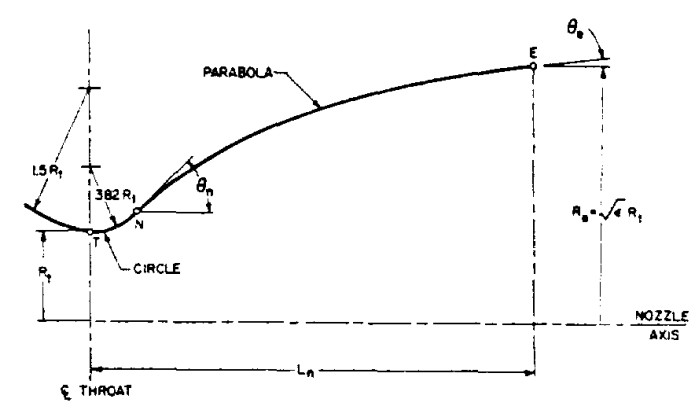 Prescribed gometry of a bell-shaped nozzle [1] |
As seen in Figure XX, the throat and the start of the bell-shaped are connected by a curve that has a constant radius of 0.385 times the radius of the throat. [1]
The inlet and the throat are also connected by a curve that has a constant radius, but this time it has a radius of 1.5 times the radius of the throat. [1]
The angle of the start of the bell-shaped nozzle is referred to as the initial parabolaangle, while the angle at the end of the bell-shaped nozzle is referred to as the final parabola angle. The value of these angles is a parameter of the used expansion ratio, but also the length of the bell-shaped nozzle. The length of the bell-shaped nozzle is often expressed as a percentage of the lenght of a cone angle that has a 15-degree half-angle. See figure below for a graph to determine the start and end angle of the bell- shaped nozzle: [1]
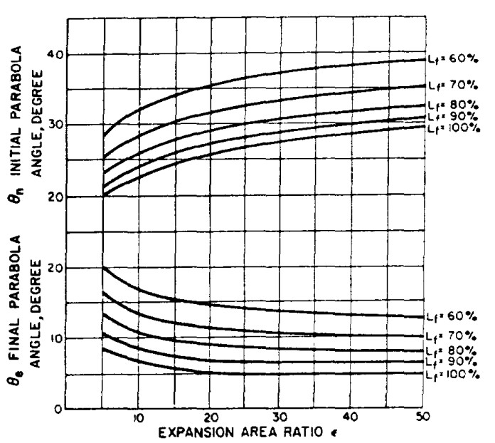 Values of the initial and final parabola angle [1] |
The parabola can be described by an equation. This equation has to fulfill the start and end points, but also the initial and final parabola angle. Therefore, the equation has four unknowns and is described as follows:
x=A* y^3+B* y^2 +C* y+D.
X is in the longitudinal direction, while y is the lateral direction. The parameters A, B, C and D are determined to fulfill the boundary conditions.
The time spent in the combustion chamber is referred to as stay time. The stay time depends on many parameters. To simplify the determination of the required combustion chamber volume, the parameter of characteristic length (L*) is defined. The characteristic length is defined according to figure XXX. The characteristic length is defined for a number of propellant combinations. [1]
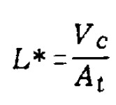 Definition characteristic length (L*) [1] |
In this equation the following parameters are defined:
- L*: characteristic length in m2
- Ax: throat area in m2
- Vc: Volume of the combustion chamber in m3
An increase in the characteristic length results in a larger and thus heavier combustion chamber. Secondly, an increase in L* leads to an increase in surface area that needs cooling and thus also an increase in thermal losses. Thirdly, an increase in L* results in an increase in frictional losses. [1]
At the throat, choked flow occurs, which is the condition where a maximum mass flow occurs for a nozzle. From this condition the throat area can be determined, as is defined by the following equation:
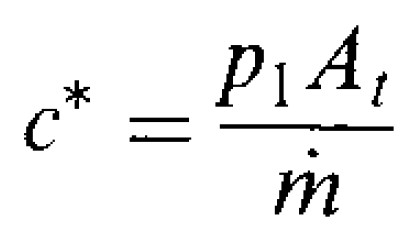 Definition throat area [2] |
In this equation the following parameters are defined:
- C*: characteristic velocity in m/s
- At: throat area in m2
- P1: chamber pressure in Pa
- m dot: mass flow in kg/s
As can be seen in the equation above, an increase in mass flow results in an increase in throat area. The throat area will decrease when the chamber pressure is increased.
[2]: Rocket Propulsion Elements - George P. Sutton and Oscar Biblarz